
Roland Super JX
I discovered synthesizer with the Roland JX8P. I never got one, but got a D50 instead. A couple years ago, I got the opportunity to buy a MKS70 (with a PG800). This synth has been running fine since I got it, and I like it a lot.Latest update
(April 2013) The assigner code has been (almost) fully rewritten. It is under beta-testing now. I bought a JX10 (which arrived with a broken display) to debug the code on the JX10 as well. This is ongoing, since I just fixed the display (was fortunate to find a S-50 display board on ebay).Story
A few years ago, I bought 4 super JX sound boards on ebay. My intent was to reverse-engineer them, as well as the assigner code (even though I didn't get a spare assigner card), and maybe improve things. Well, it is now time to share some of these experiments.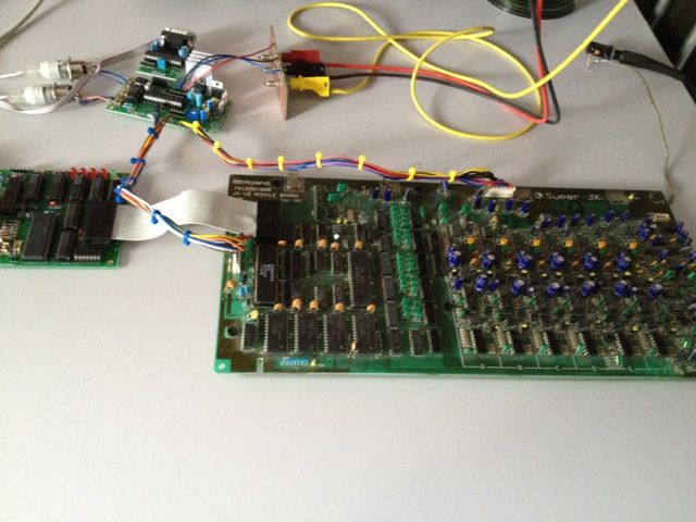
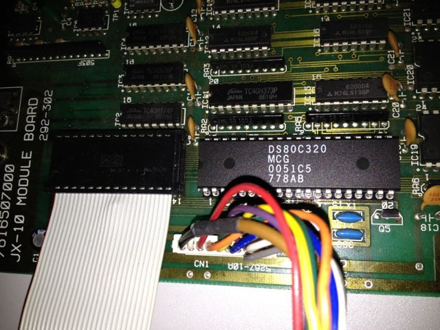
My test setup is shown above. I have built a little assigner board (based on a PIC18). It has midi in/out, PG800 in, and provides power to the sound card. I added a SPI/serial converter so the assigner can provide debug output (much more comfortable than a in-system debugger, since this code is almost never changed)
Disassembling
The sound card uses a 8031 CPU, while the assigner uses a hitachi 6303 chip (6809 compatible). Disassembling the sound card code without understanding what the assigner sends was a bit challenging, so I decided to work on both at the same time. (Note that the JX-10 code has already been hacked by Colin Fraser, and his notes were a nice start). Any developer can quickly find that the assigner code is ugly and not very well structured. Guessing what the code does was a nightmare, so I wrote an emulator, with plenty of options (breakpoints, conditional breakpoints, tracing, scripting, etc...) so I could quickly find out what the assigner is sending, how and when. The 8031 code is very different, and is correctly written (it has 2 minor bugs, never discovered before as far as I know). After many evenings (it took more than one year, but I wasn't really working often on this), the 8031 code is now fully understood. The assigner code is not yet fully disassembled, but I have (for now) no reason to spend time on this. Some sample output from my emulator: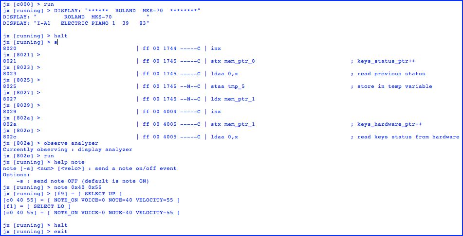
Enhancement
After having understood how the 8031 code works, I wanted to replace the 8031 CPU with a more modern version, and I got a few Dallas 80C320 on eBay. They are pin-to-pin compatible, and run much faster than the original 8031. Furthermore, even if the speed bump wasn't enough, I could still replace the 12MHz crystal. My problem was to test the rewritten code... Burning an eprom each time something is changed was not an option, so I needed an eprom emulator. These devices are pretty expensive, and the ones I found didn't really suit my needs, so I decided to build my own. I found one based on a PIC, and enhanced it so that it uses USB, and has a battery to keep the RAM content when the device is power-cycled. This took again a few evenings, and I am really pleased with the result :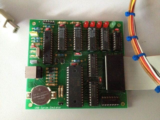
Armed with the eprom emulator, my next step was to run the original code with the 8031. This worked immediately (as expected). I followed with the rewritten code, targetted for 8031. The result also worked very quickly (after a long session to find a bug). Obviously, the sound card still sounds the same.
Upgrading to 80C320
I replaced the 8031 with a socket, and installed a 80C320.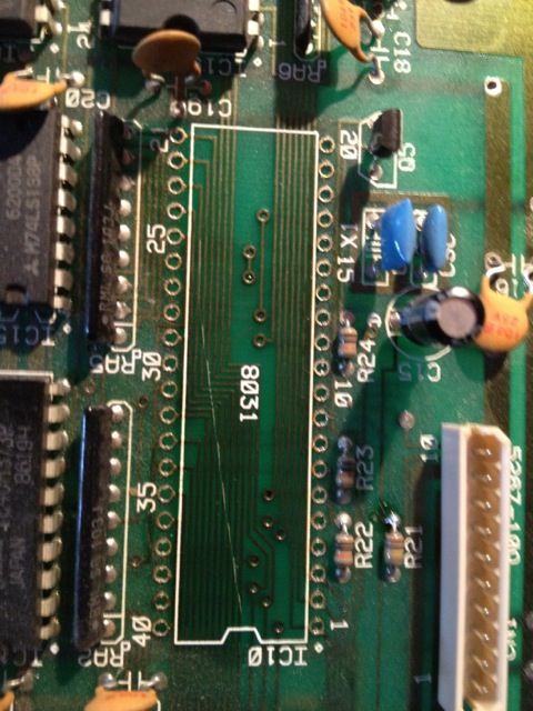
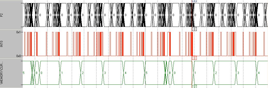
The adapted code ran immediately. A few explanations about "adapted code". The original 8031 code doesn't use interrupts, and runs the code in a loop. Each loop takes almost 10ms. The various voltage controls (VC) are updated throughout the code. The only interruption used is the serial port. The new code, on the 80C320, must respect the same timing, so timer2 is used. In simulation, the timing looks like this on the 8031:
and on the 80C320 (voices 0-2 runs every 10ms, starting at t=0ms, while voices 3-5 runs every 10ms, but starting at t=5ms. The reason for this is that some VC are updated twice, the first time with an interpolated value)
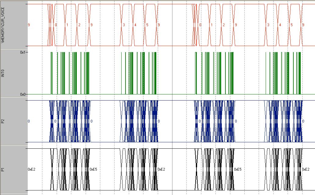
The interesting data is "CUR_VOICE", which is some debug code that I added to show which voice is being updated. (0-5 are the 6 voices, 6-8 are common routines (LFO, etc...)). On the 80C320, I added value 9 to show when the CPU is idle. It can be seen easily that the new CPU is idling half of the time, which gives plenty of time to add new features! Also, the 8031 memory (+ external 256 bytes in the 8155 chip) was almost fully used. The 80C320 comes with an extra 128 bytes, which is exactly what we needed.
Further work
I am now thinking and gathering input about the next steps. What should I add to the current code? Things that come to mind:- more envelopes : adding 2 new envelopes should be easy to do. DCO1, DCO2, MIXER, VCF and VCA could select from ENV1..ENV4.
- more than 4 "key follow" tables
- more LFO : add a 2nd or 3rd LFO. Add the option to have it free running. Maybe a 4th LFO, being a combination of LFO2 and LFO3 to form more complex LFO waveforms.
- PWM : this would be a hardware mod, but it should be relatively easy to do. To do this, 2 new CVs must be created (the hardware has some spare ones), and a few comparators should be added. The PWM duty cycle could be affected by an envelope and/or LFO.
- ???
Comments/feedback is very welcome, as always.