
Why ?
I didn't have a capacimeter nor an ESR meter, so I decided to build one.After searching the internet for a while, I found an Elektor project doing almost exactly what I wanted (it's available here). It uses 2 microcontrollers (PIC16F877@20MHz and PIC16F84@4MHz), programmed in Basic. One PIC is enough to do this, using the built-in PWM and the capture module.
So I decided to simplify this design and build my own, using a single PIC16F876 that I had around. To measure the capacitor charging time, I am using the capture module instead of polling, and the square signal is generated using the PWM module.
Measuring capacitance
Measuring is done by a 555 in monostable configuration. Tree ranges are obtained by using 3 resistors, which are selected by the microcontroller. Each resistor is connected in series with a precision variable resistor, to allow calibration.
Measuring ESR
A constant current is applied to the capacitor, using a 100kHz square signal. If the capacitance is high vs the frequency, the voltage appearing accross the capacitance is resulting from the ESR. This voltage is rectified and applied to the A/D converter of the PIC.The microcontroller can also apply a DC to the capacitor, in order to measure its resistance in DC.
Schematic and source code
The schematics (in pdf format) and the source code are available in the download section.The PIC code is composed of the following files :
- main.asm
- lcd.asm
- delay.asm
- capa.inc
- macro.inc
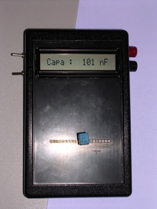
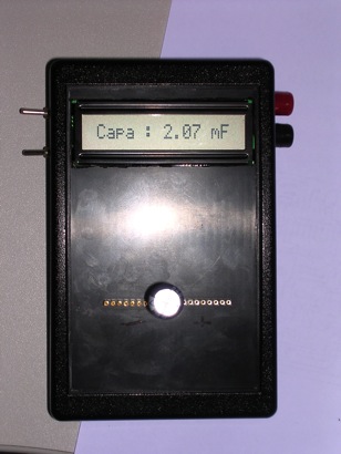
In capacitance mode, the pF range is selected first. A measure is made. If the timer overflows, the next range is selected (nF) and so on (uF and mF). Note that in the pF range, 4 measures are made and averaged. When the capacimeter is powered-on, the probe capacitance is measured, and is automatically subtracted from the next measures.
In ESR mode, AC and DC measures are made. In AC, the PWM is turned on and a measure is made after 100ms. Then, DC is applied, and again after 100ms, a measure is made. Once the two measures are available, results are shown on the LCD.
Calibration
Capacitor mode is calibrated by measuring precision capacitors (1% or less). Simply connect the capacitor, and run. Then adjust the precision variable resistor to read the correct value on the LCD.ESR mode is calibrated by short-circuiting the probes. We need to read 0 in both AC and DC. The program should store the zero values in eeprom. Since this only needs to be done once, the program should detect, at boot time, if the eeprom has already been programmed. If not, it should ask the user to short-circuit the probe, calibrate, and store the values once for all. [This code has not been completed, but the various routines are in main.asm]
- Switch to capacitor mode.
- Connect 470pF 1%
- Turn P3 to read 470pF
- Connect 100nF or 220nF 1%
- Turn P4 to read the correct value
- Connect 10uF or higher
- Turn P2 to read the correct value
- Switch to ESR mode
- Short-circuit the probes
- Connect a voltmeter to pin 7 of LF412
- Adjust P5 to read 40mV
- Connect a 10ohm 1% resistor
- Adjust P6 to read 10.0
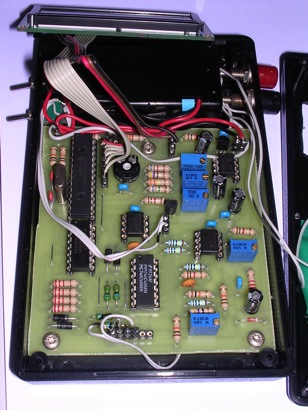
PCB
A PCB was made, single-sided. It matches the size of a plastic box available from Farnell. It is also available in the download section.Wiring
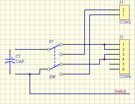
I receive many questions about the wiring, from the PCB to the switch and the connectors. A new schematics has been added to the zip archive. A snapshot is visible below. Please double-check with your LCD. The pin numbers may not match !!!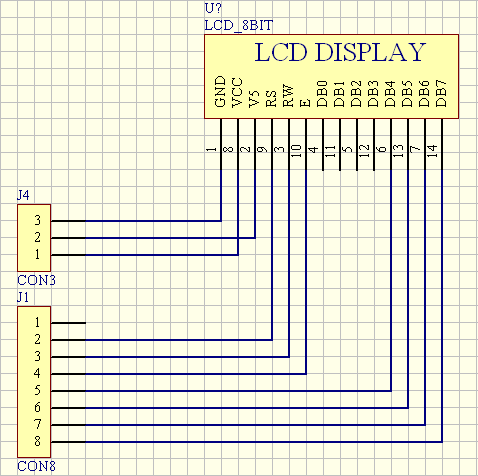
You can build it too !
As of today (10/10/09), over 50 people have successfully built this ESR/capacimeter !