
Multi protocol IR decoder
Often, in PIC projects, an IR input method is desirable. Often, IR remote controls are available from the junk yard, or from places like Weirdstuff. People often don’t have time to reverse-engineer the IR protocol, or are just too lazy to implement routines to decode the IR stream.A nice place with plenty of information about IR protocol is www.sbprojects.com. The author proposes PIC implementation to decode various protocol (here).
We propose here a different approach : multiple protocols are supported (at the same time), and the IR detector is connected to the capture module of the PIC, which allows to easily measure the length of the IR pulses. Once a pulse has been detected, an interrupt is generated, and the decode logic is called. Each protocol is simply a state machine. If an IR frame is received correctly, a structure is updated with the decoded information :
- protocol
- command (8 bits)
- address (16 bits)
- extra information (8 bits)
Supported protocols.
The protocols supported currently are the following :- Raw (save the pulses durations in memory)
- Nec
- Nec Extended
- JVC
- RC5
- RC6
- Sony 12bits
- Sony 15bits
- Sony 20bits
- Sharp
- Pace
How to use ?
The source code is available in the download section. The code is written in C, but can be easily translated in assembler.The relevant files are ir2.c and ir2.h. You will have to edit ir2.h to select the protocols that you want. main.c contains an example where the IR routines are initialized, then the main loop waits until a frame is decoded, and displays it on the LCD.
How to adapt the code to a different oscillator frequency ?
The oscillator used on PICDEM2 runs at 4MHz. In the PIC, the 4x PLL is enabled, so we run at 16MHz. Timer1 is configured in 16 bits mode, and overlaps at 0x10000. With Fosc/4 = 4MHz, that's 16.384ms. This value should be long enough to detect a timeout while we are waiting for a pulse.Next, the various pulse settings defined in ir2.h. For example, let's take RC5. A short pulse is 889us. At Fosc/4 = 4MHz, 1 tick of timer1 is 0.25us. Therefore 889us = 3556 ticks. But we don't need 16 bits precision, so the comparisons are made using the upper 8 bits of the capture register (CCP1H). Here, 3556/256 = ~13. To detect a valid RC5 short pulse, we find in ir2.h the following defines :
- RC5_MIN_PULSE 10
- RC5_MAX_PULSE 16
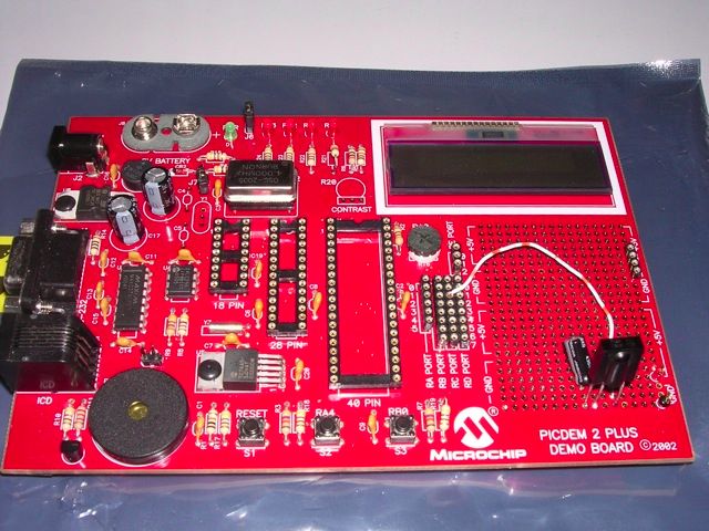
Hardware
I receive several questions per week about the hardware required for this project! I hope that the following explanations will help.The project was developed using the PICDEM2 board from Microchip. The PIC is a 18F452, but any PIC18 will work. Connect the IR receiver to CCP1 (RC2 for the 18F452). The crystal/oscillator is 4MHz, but the PLL is enabled, therefore the PIC runs at 16MHz. You can, of course, change the frequency, but you will have to adapt the various parameters. The LCD is connected on PORTD (4 bits mode), and PORTA (RA1=E, RA2=RW, RA3=RS). All IR receivers should work (I scavenge them from old VCR !). The model I used is a TSOP12xx (datasheets available in the download section).
More questions?
Email me.Happy IR decoding with your PICs !!!