
Nixie Clocks
Many people have gained interest in the old nixie technology. The popular, and growing, yahoo group NEONIXIE-L is a proof.The first clock
I have had fun creating a first nixie clock, which I should have described in these pages, but never really bothered, because it was "just another nixie clock". But it allowed me to understand the techonology, with its challenges. The source code of this first clock, which was full featured, is still available in the download section. This clock was a six tubes clock, multiplexed 2x3, with fading, IR remote control and DCF77 support.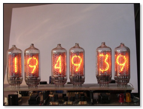
The second clock
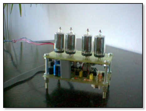
I had a few Japanese nixies (only 5, unfortunately) Rodan GR116D, and decided to create another clock, 4 tubes, smaller, to sit on my desk at the office. This time, I tried to maximise the use of a PIC18 microcontroller, so the PIC would be in charge of generating the high-voltage (so no need to a MAX1771 or MC34063), maintain the real-time clock (saving a DS1307 or other RTC chip). However, this would have been yet again "just another nixie clock".
As we all know, the software is what will make the difference! So, this clock has a very sophisticated firmware used to drive the nixies :
- Each tube has its own settings : brightness, fading, main value, alternate value.
- Each setting can be set automatically or directly. For example, the main value of a tube can be "unit digit of current time's seconds", or "brightness auto-increment", etc...
- Every quarter of a second, a set of actions can be evaluated. For example, you can define that every minute, when seconds equal 50, the date is displayed. But you can also define that the date comes after emptying the display with a roll effect, with fading, and decreasing brightness. Possibilities are endless.
The firmware
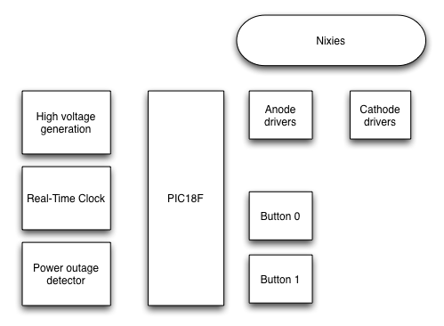
This article will focus on the software, which can be downloaded in the download section. The software is free to use, but if kits are made with it, I only ask to receive one kit to grant the permission to redistribute for commercial purposes.At the heart of the clock, we find a PIC18. Many of its internal devices are used :
- To generate the high-voltage, TIMER3, A/D and PWM (which uses TIMER2) are used.
- TIMER1 is used for the Real-Time-Clock (RTC), and buttons debouncing.
- TIMER0 is used to refresh the nixies and multiplex.
- Interrupt 0 (INT0) is used to detect a power outage.
- Interrupts 1 and 2 (INT1, INT2) are still available to add DCF77 and/or an IR decoder.
- The USART also remains available for later use (bootloader and/or external reprogramming of the clock animations)
The main functions and the hardware are described in the dedicated pages :